

Let's Split Build Log
Build log of the 40% Let's Split keyboard
Before jumping to pictures and build steps, I'd encourage you to read the bottom of this post first where I talk about everything that I did wrong. This isn't an advanced board to make however I learned by failing and hopefully, you can avoid the same mistakes! Let's get into it.
I've always been intrigued and excited by small keyboards. I've written a lot about keyboards and a running theme is that they're getting smaller and smaller. One of my previous build successes the 'Planck' was loads of fun and I enjoyed learning how to make the most of 40% boards with extreme layer optimisation. However, the compactness and rigidness of the keyboard didn't agree with my natural posture which unfortunately put a lot of strain on my wrists.
One of my original aims with getting into smaller boards was the ergonomic benefits and although the Planck seemed perfect to me, it killed me that it was killing my wrists. After some searching, I came across what seemed like an ideal solution. Enter 'Let's Split'. This board is basically the product of taking a circular saw to the Planck and chopping it in half. It's a split keyboard with two sides of 6x4 ortholinear columns allowing you to angle both halves to be as comfortable for you as possible.
If you're reading this post then you're one of two people. You've either already acquired the parts required to build this board in which case feel free to skip below, or you're thinking about building one and doing research. If you're one of the latter category I urge you to take the plunge because this keyboard is a load of fun both to build and use. It did take me further getting used to and massively highlighted my lack of discipline with regards to 10-finger typing but this board ticked all boxes and more. Let's get into the build!
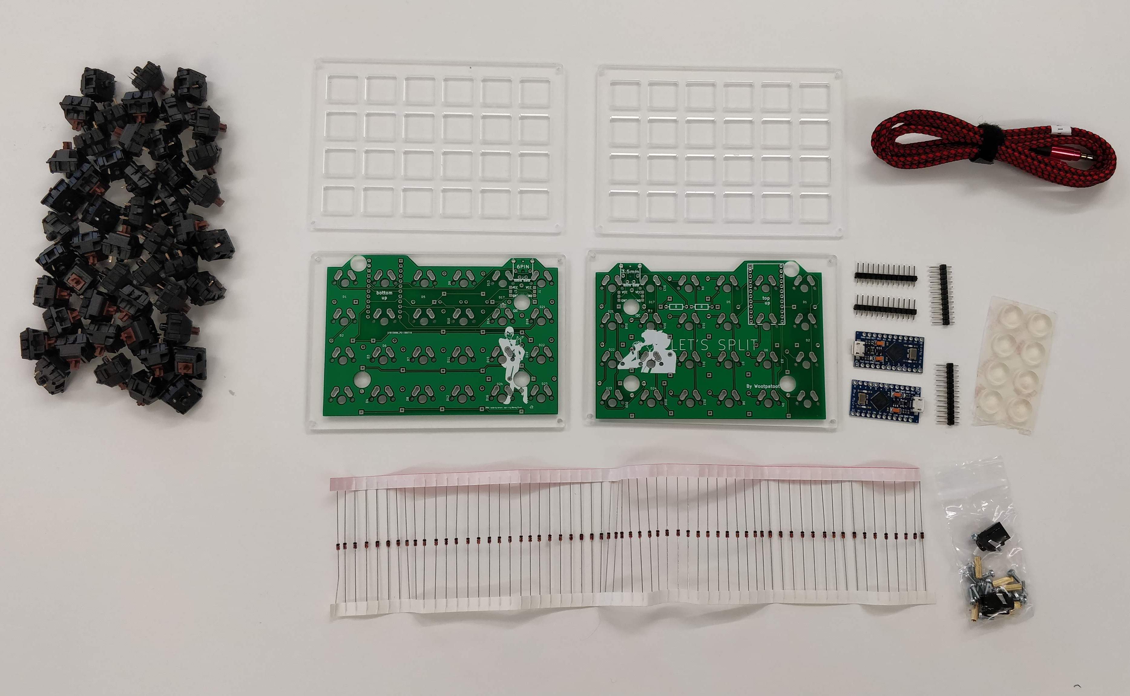
Parts required
Several websites will provide the following parts for you such as mechboards but in case you wanted to source the parts for cheaper you will need:
- 2 PCBs (v2)
- 2 5V/16MHz Pro Micros
- 4x12 header pins or (recommended) 4x12 ultra-low profile Mill-Max Header sockets, 4x12 header connectors, 48 connector pins
- 48 through-hole diodes (1N4148)
- 2 TRRS jacks (CP-43514-ND)
- Plate & case (sandwich design)
- 8 10mm M3 standoffs (required for case)
- 16 6mm M3 button head or flat head screws (required for case)
- 48 Switches
- TRRS cable
Equipment required
- Soldering iron
- Solder
- Screwdriver
- Side-cutters/similar
- Solder removal pump (optional but recommended)
- Flux (optional)
- Isopropyl alcohol and a toothbrush for cleaning flux residue (optional but advised if you used flux)
- Helping hand for desoldering (optional)
Now... We Build!
This keyboard is a split keyboard. To keep this build log as simple and succinct as possible I'll only be showing how to build one half. You will then have to repeat the steps for the other half. I would recommend not doing both halves in parallel in case you make the same mistake twice; It will be a lot easier to correct if you realise you have done something wrong only once. As a further note and disclaimer, I built this board two years ago and my soldering technique wasn't the greatest back then. Take a look at this for a 101 on good soldering technique.
Before we properly begin, another reminder to scroll to the bottom of this post to check out the mistakes that I made originally so that you can learn from them and not do what I did. This project became a lot more expensive and time-consuming than it should have been because I wasn't paying attention. Let's start!
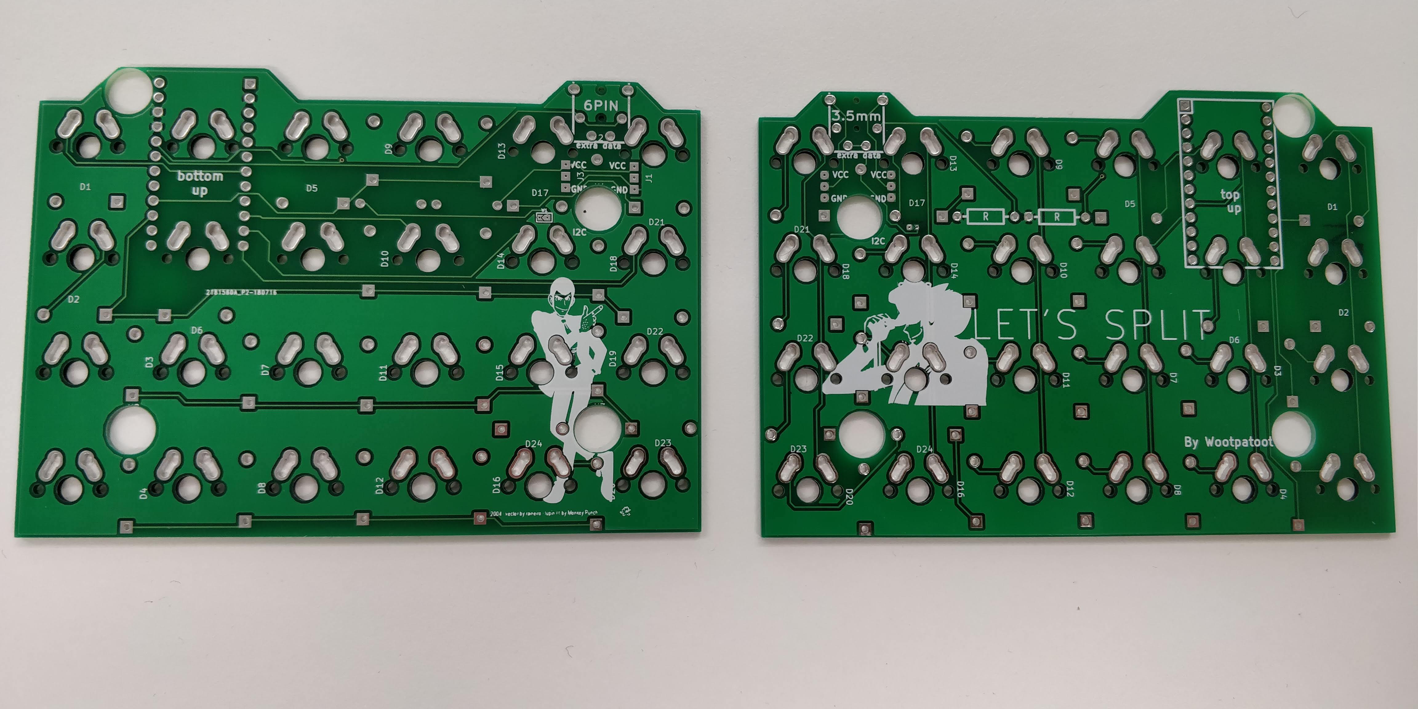
Step 1. Preparing the diodes
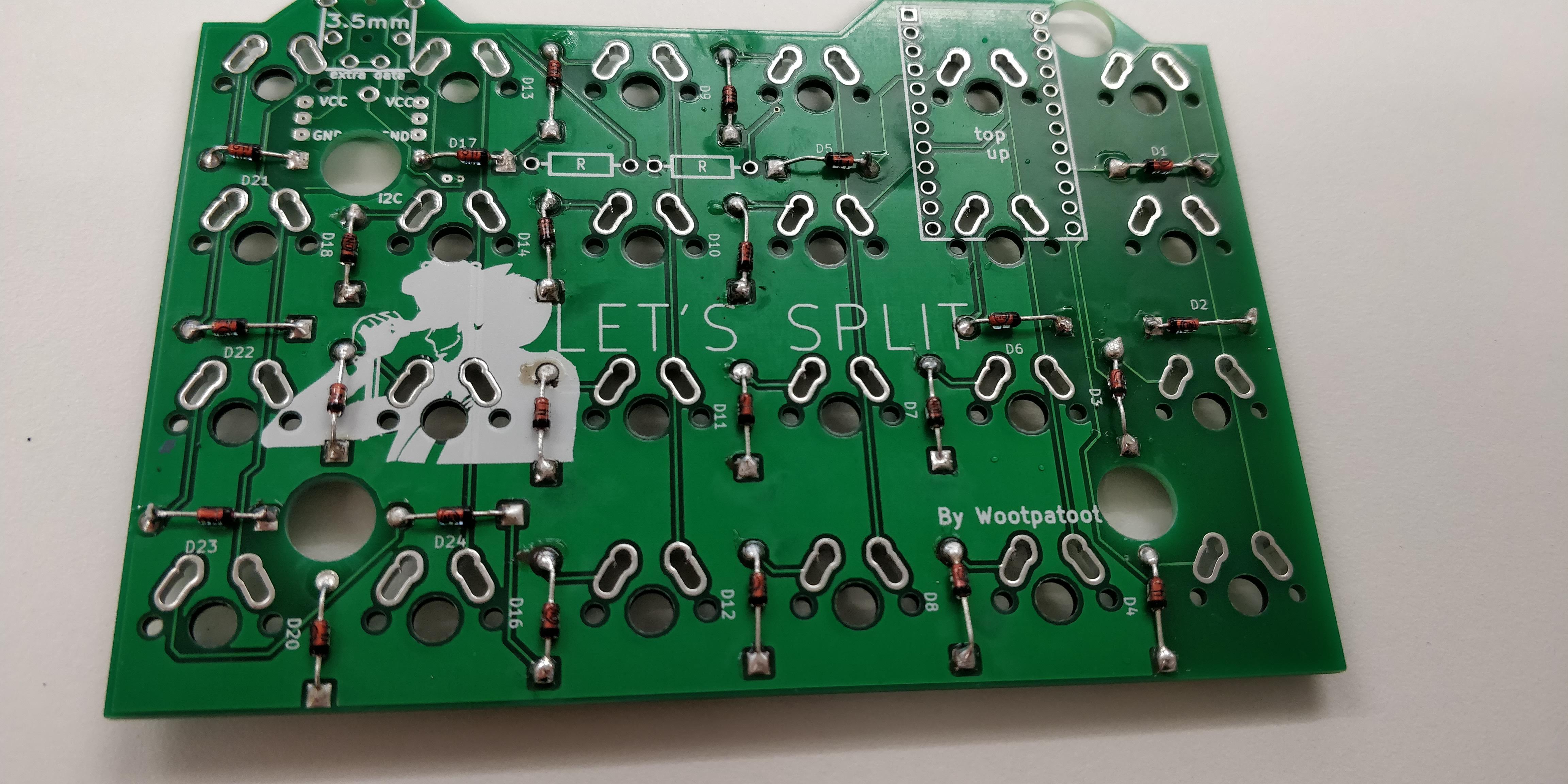
Mount the diodes through the holes in the PCB. The holes come in pairs with one of them being square-shaped. Diodes allow current to flow in one direction only so you want the black line on the diode facing the square pad.
It might take one or two attempts to bend the diodes cleanly but to keep the diodes in place, bend the legs at 90-degree angles so that they don't move.
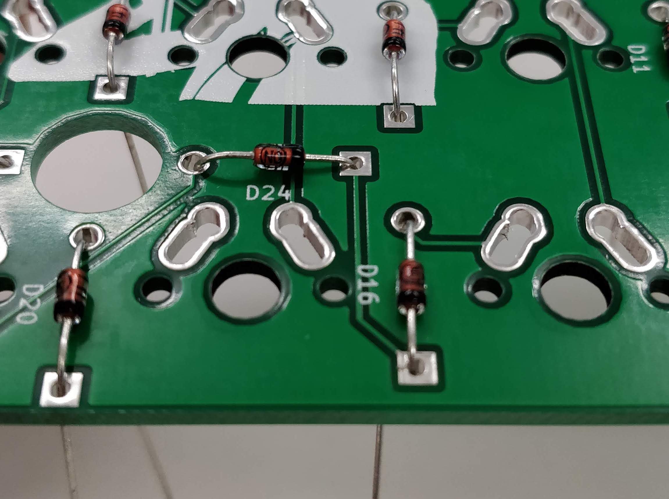
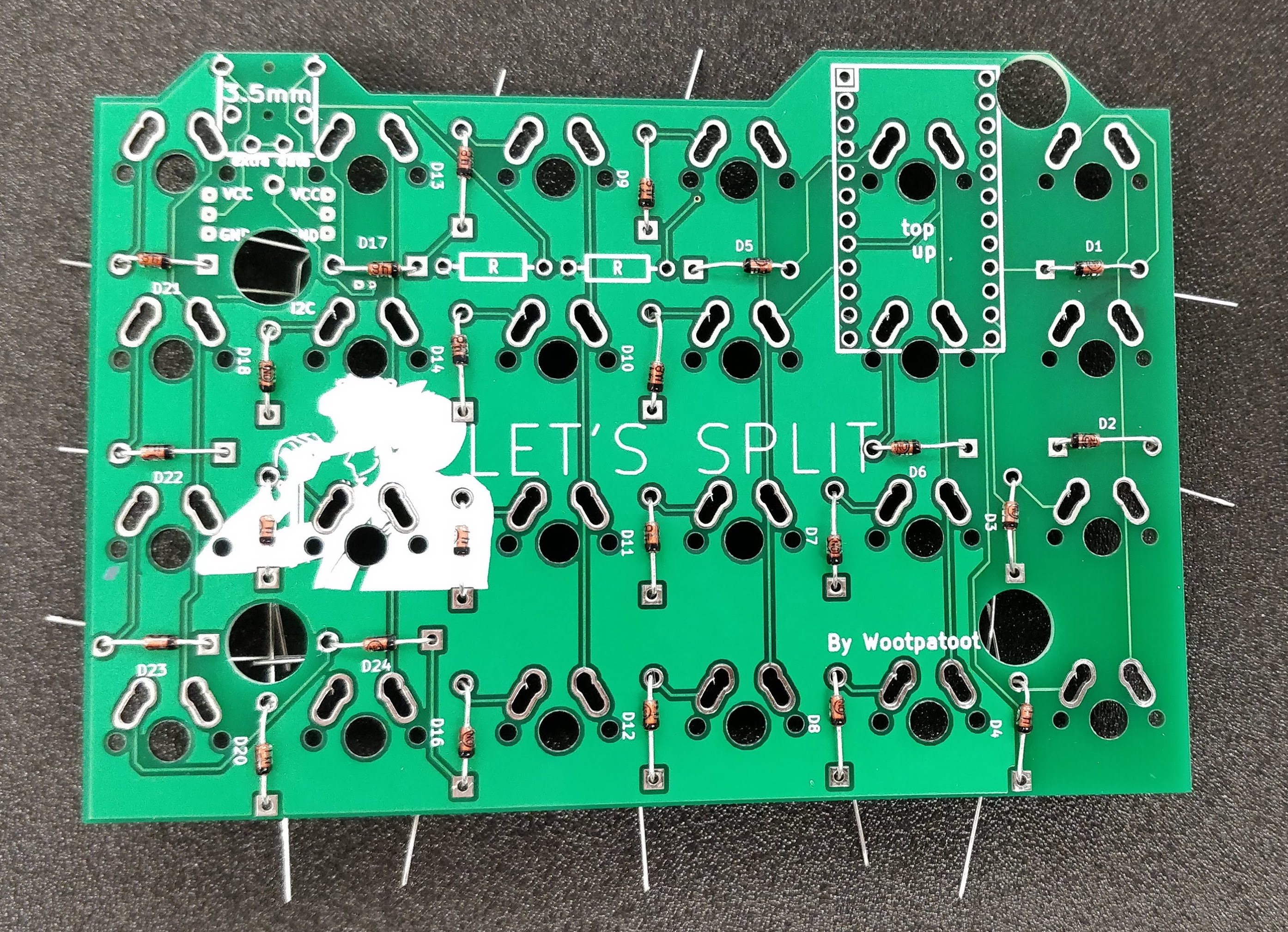
Step 2. Soldering the diodes
If you have flux, apply it to all of the joints to promote the flow of solder. Take your iron and one by one solder the diodes in place followed by trimming the extra length from the legs. You can throw these away if you don't need them for other projects but they can come in useful to make header pins (at a later optional stage in step 4).
Once all of the diodes are soldered and legs trimmed we're ready to solder the TRRS jack in place so that both sides of the keyboard can communicate with each other! If you did use flux you might want to take some Isopropyl alcohol and a toothbrush and scrub the board clean of flux residue.
Step 3. Soldering the TRRS jack
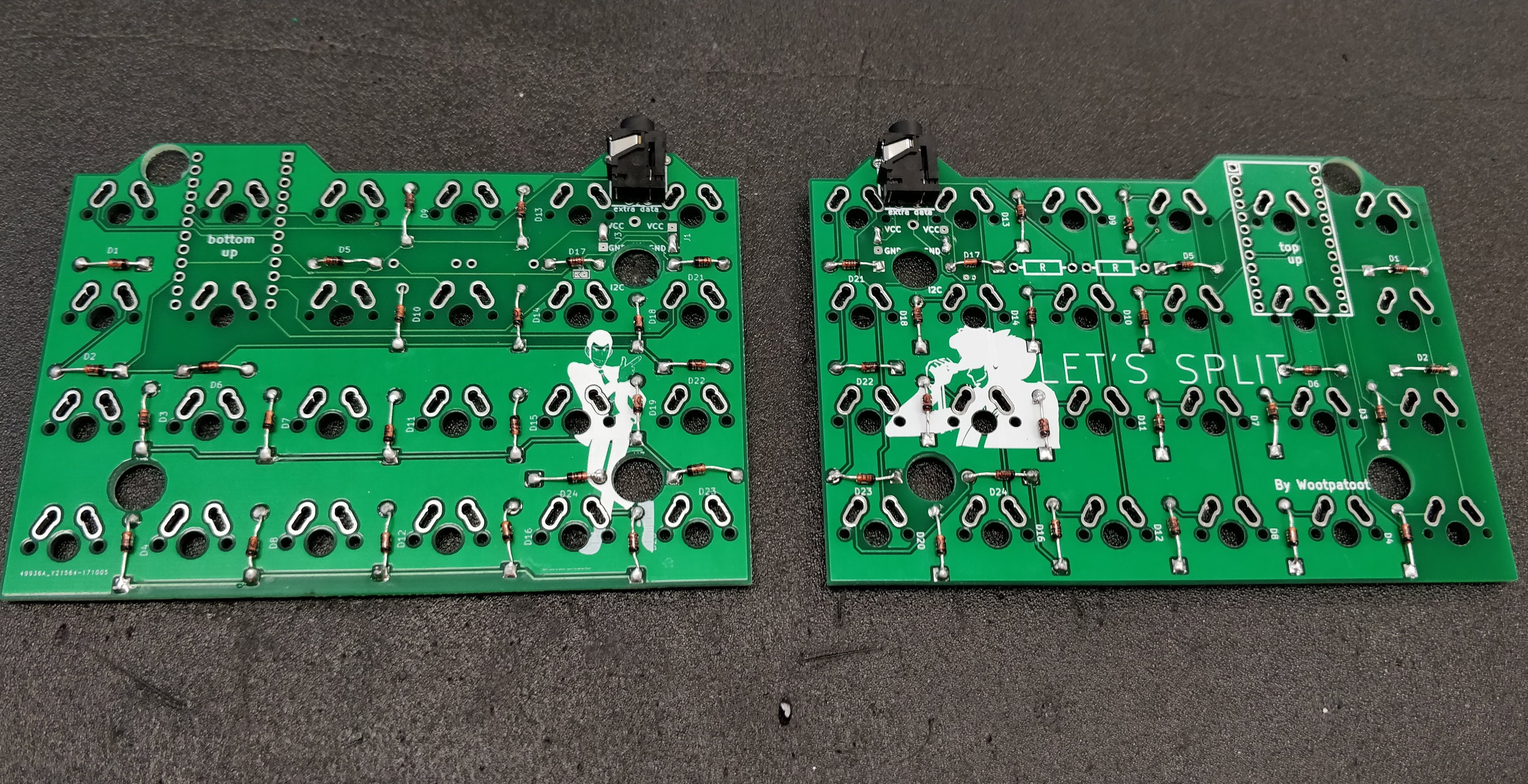
The TRRS jacks are required to communicate with each other. Place the jacks in the holes on the bottom side of the board and solder them on the PCB as shown in the image.
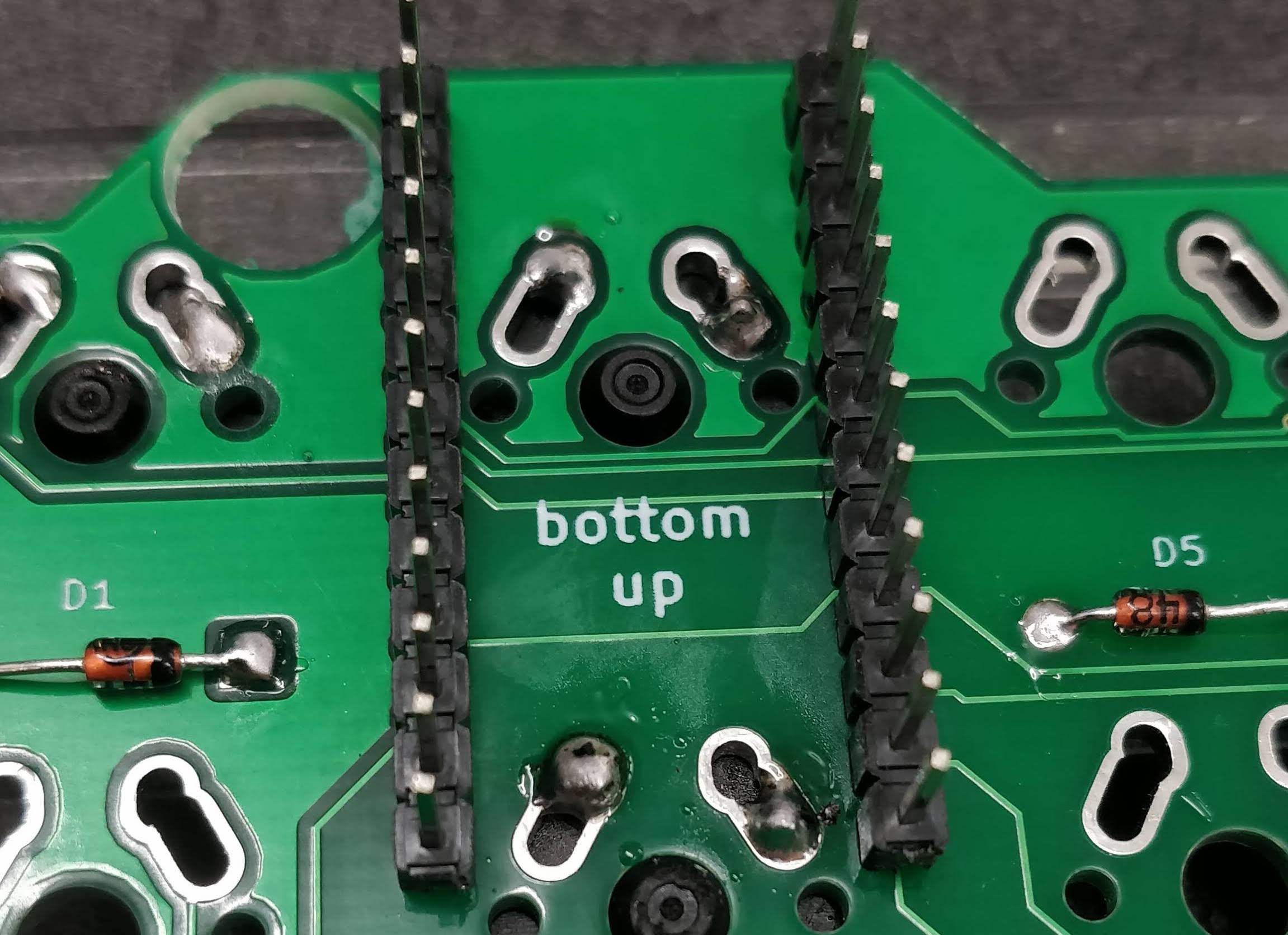
Step 4. Soldering the microcontroller header pins
This step has two options.
- Solder the header pins (which this guide will show)
- Solder sockets to the board (this will allow for easy removal/replacing of the microcontroller if it breaks or you want to upgrade). This is recommended but slightly more complicated. If you want to do this option then you can follow step 7 - 10 of the Corne build guide before returning to step 5 in this guide.
On the same side as the TRRS jack, place the header pins in the 24 smaller holes on the underside of the PCB and solder on the reverse. Take your time with this step and be careful not to bridge connections
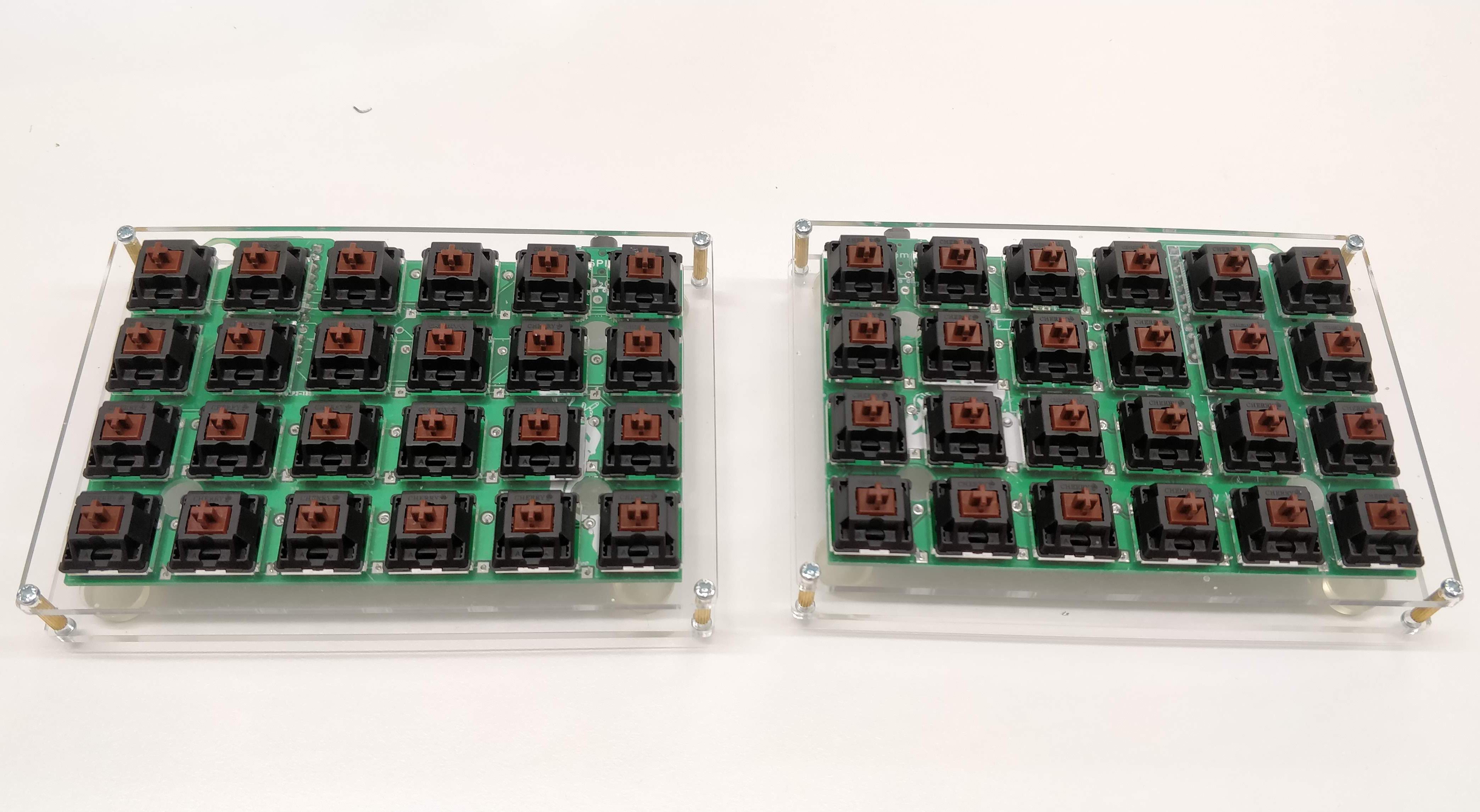
Step 5. Solder the switches between the top plate and the PCB
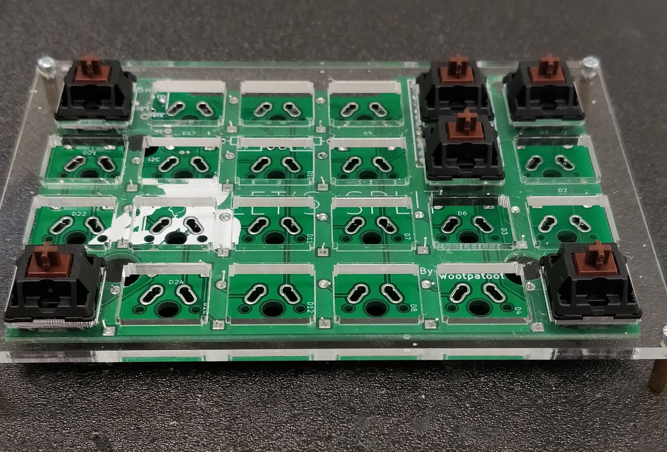
Starting with each corner take the top plate and insert a switch into each hole until they 'click' into place. Once you have each corner in place you can solder them in on the underside of the PCB followed by the remaining switches.
Step 6. Test the microcontroller
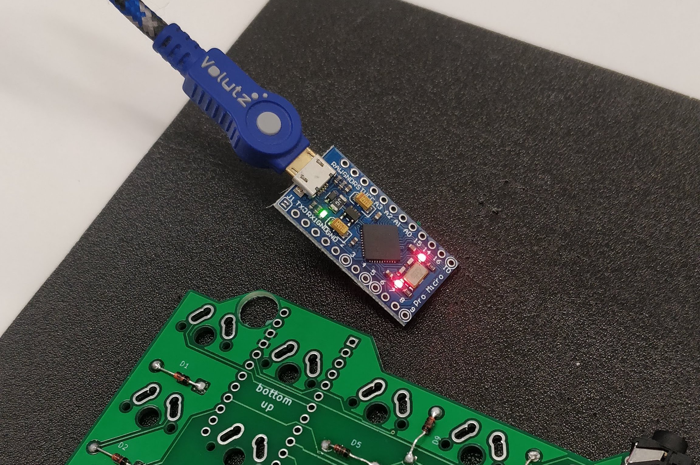
Before we solder the microcontroller to the header pins we should test that it works! It'll save a lot of time and careful painful removal later if it turns out to be a dud. Connect it to a USB cable and if the light remains on then you're good to go.
Step 7. Solder the microcontroller
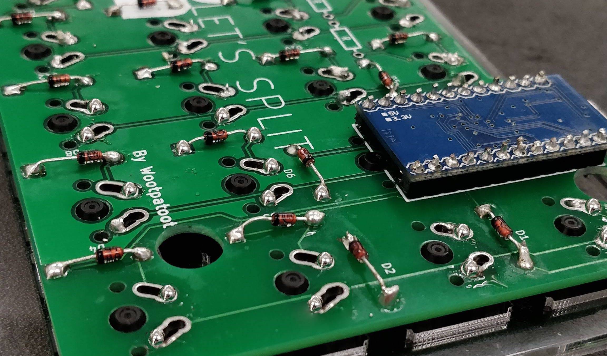
Follow this step carefully. Ensuring that you have soldered a switch first under where the microcontroller will sit, place the microcontroller in the following way:
- On the left PCB the microcontroller should be smooth side up
- On the right PCB the microcontroller should be component side up
This will dictate and control the direction i.e. whether it's the left side or right side of the keyboard.
Step 8. Screw the bottom plate in place
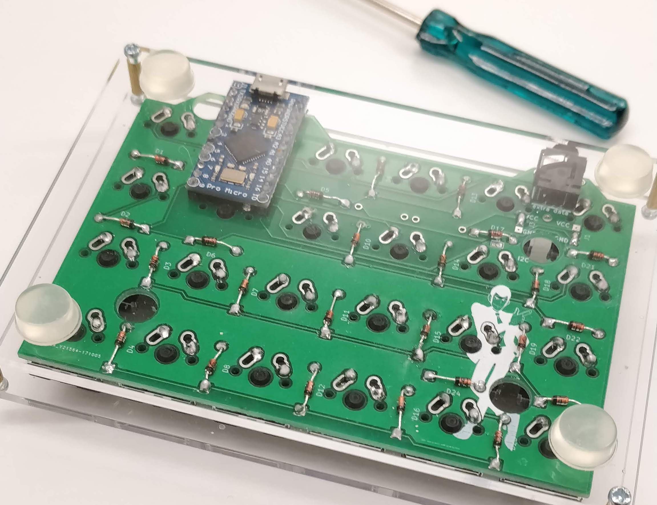
Take the bottom plate, screws and M3 standoffs and screw the top and bottom plates together. The keyboard will likely slide around your desk depending on the surface so it's advisable that you also stick on rubber feet to the bottom of the case to give the board some grip!
Step 9. Repeat steps for the other side
If you weren't already doing so as you went along, repeat the above steps for the other side of the keyboard being careful with the orientation of some components like the microcontroller detailed above.
Now we're ready for the finishing touches...
Step 10. Add the flare 🕺
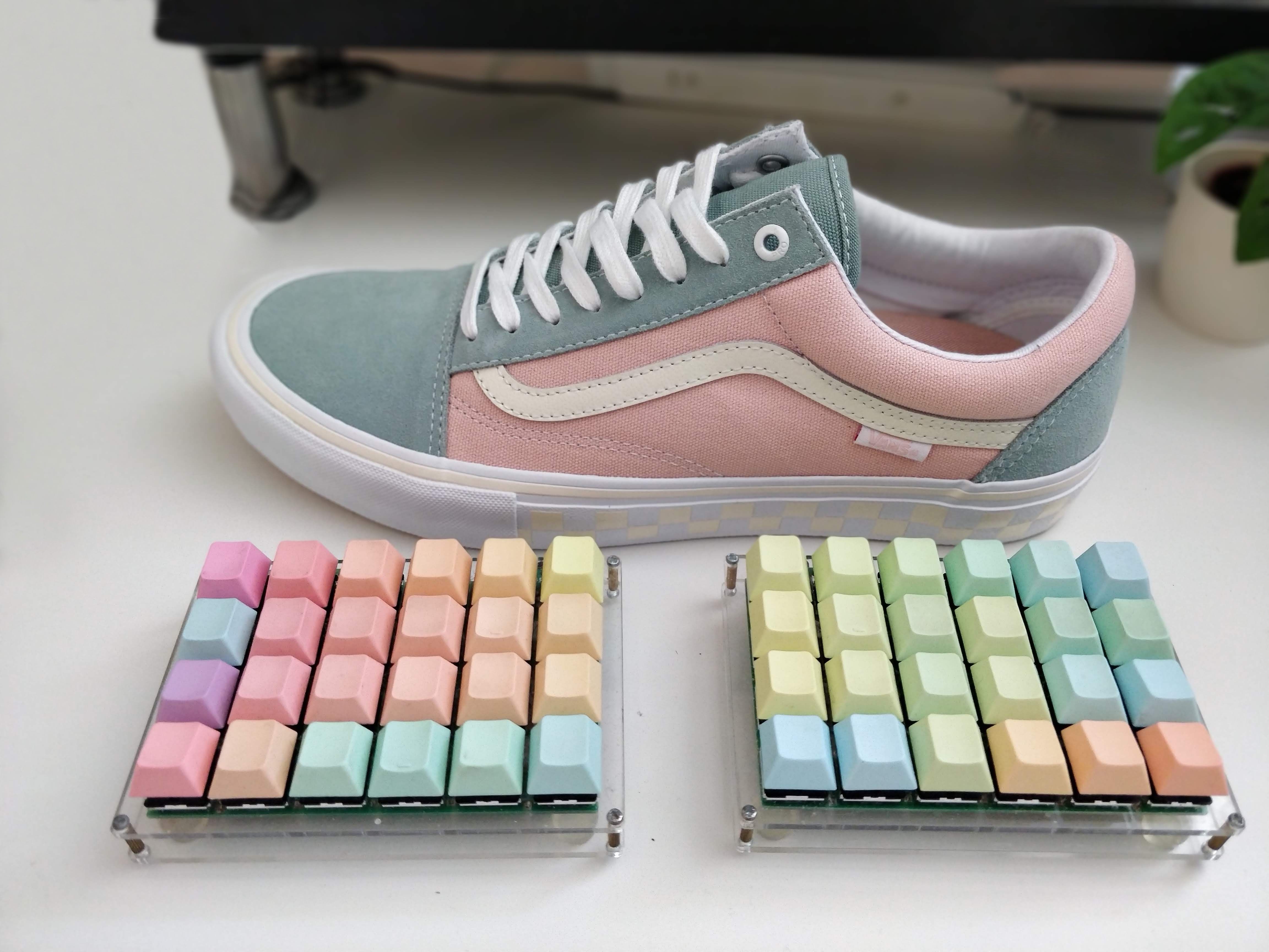
Dress it with your favourite keycaps and admire! (Matching shoes are optional).
Mistakes that I made
Thanks for giving this section a read. I don't feel like too many people would be keen to showcase their mistakes but I hope the candidness of this is appreciated and you can learn from them.
Mistake 1: Not socketing the microcontroller
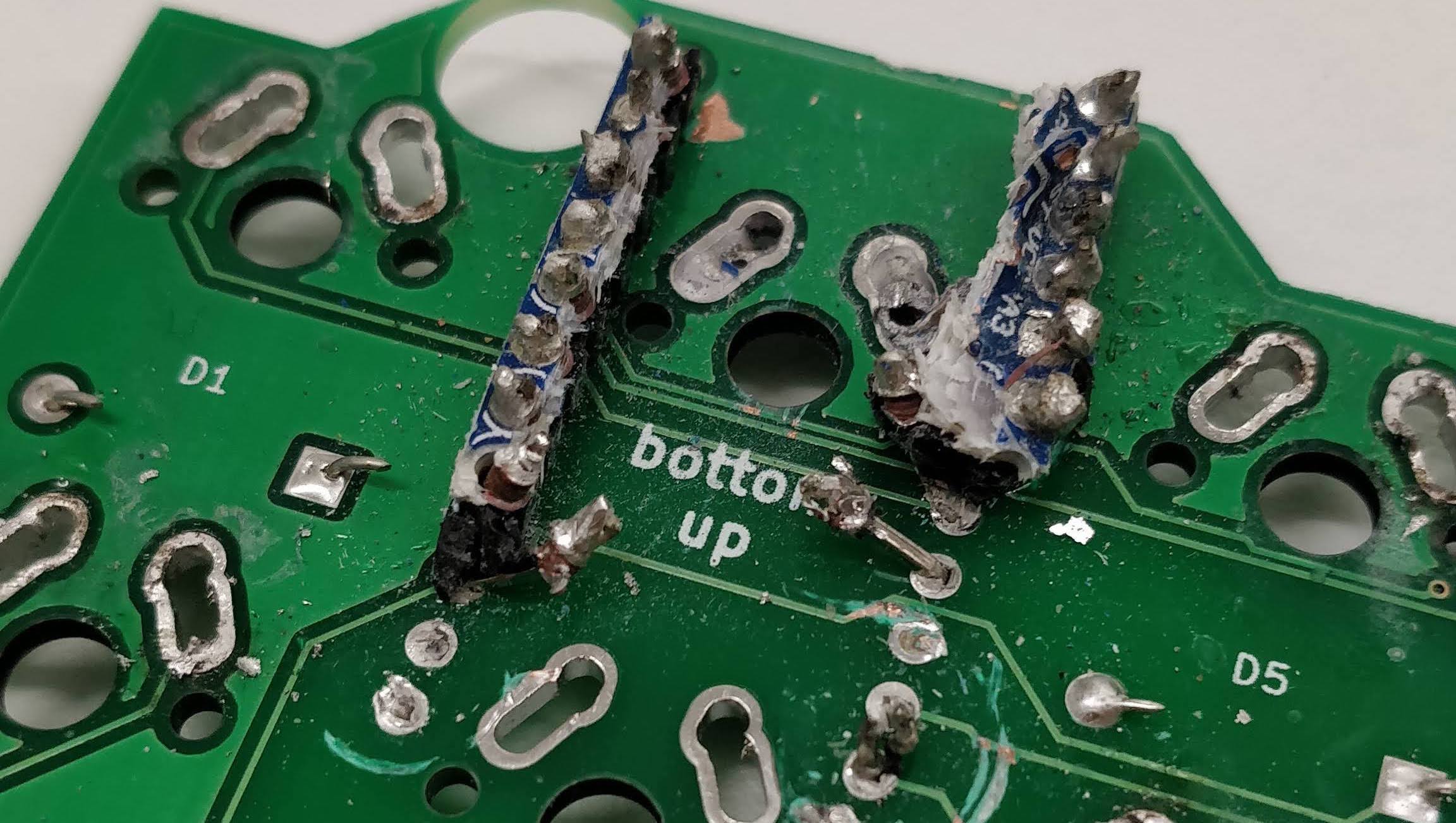
My main mistake was that I got way too excited and didn't read the manual first. In step 7 I noted that you must first make sure that the switches are soldered before soldering the microcontroller (at least the switch the sits under it). I did not do this and went ahead and soldered the microcontroller immediately. This would not have been an issue had I socketed the microcontroller (option #2 in step 4) as I would have easily been able to remove it without needing to desolder it from the board. As you can see, I gave up and tried to cut the microcontroller free with the idea that I could more easily clean up afterwards. This was the result. I had to order a new PCB and start again...
The lesson here was always to put the time and effort into socketing complex components like microcontrollers. Oh, and reading the damn manual.
Final thoughts and learnings
This board was fun to build but made more complicated by not using sockets for the microcontroller meaning that mistakes were a lot more permanent. I built this board a few years ago and my soldering wasn't great and as good as it is now, but it was a good board to practice on and it didn't give me any issues from cold joints. It was very forgiving and I'd recommend this to anybody starting out with electronics and building their own keyboards.
The angles made possible by having a split keyboard is so much more ergonomic and comfortable that I don't think I could ever go back to a regular keyboard and I'd recommend anybody to give it a try too.


